
Mission
Hardware
Documentation
Three generations of competition-proven Mars rover hardware. Engineered across two countries, tested in Utah, refined for the next launch window.
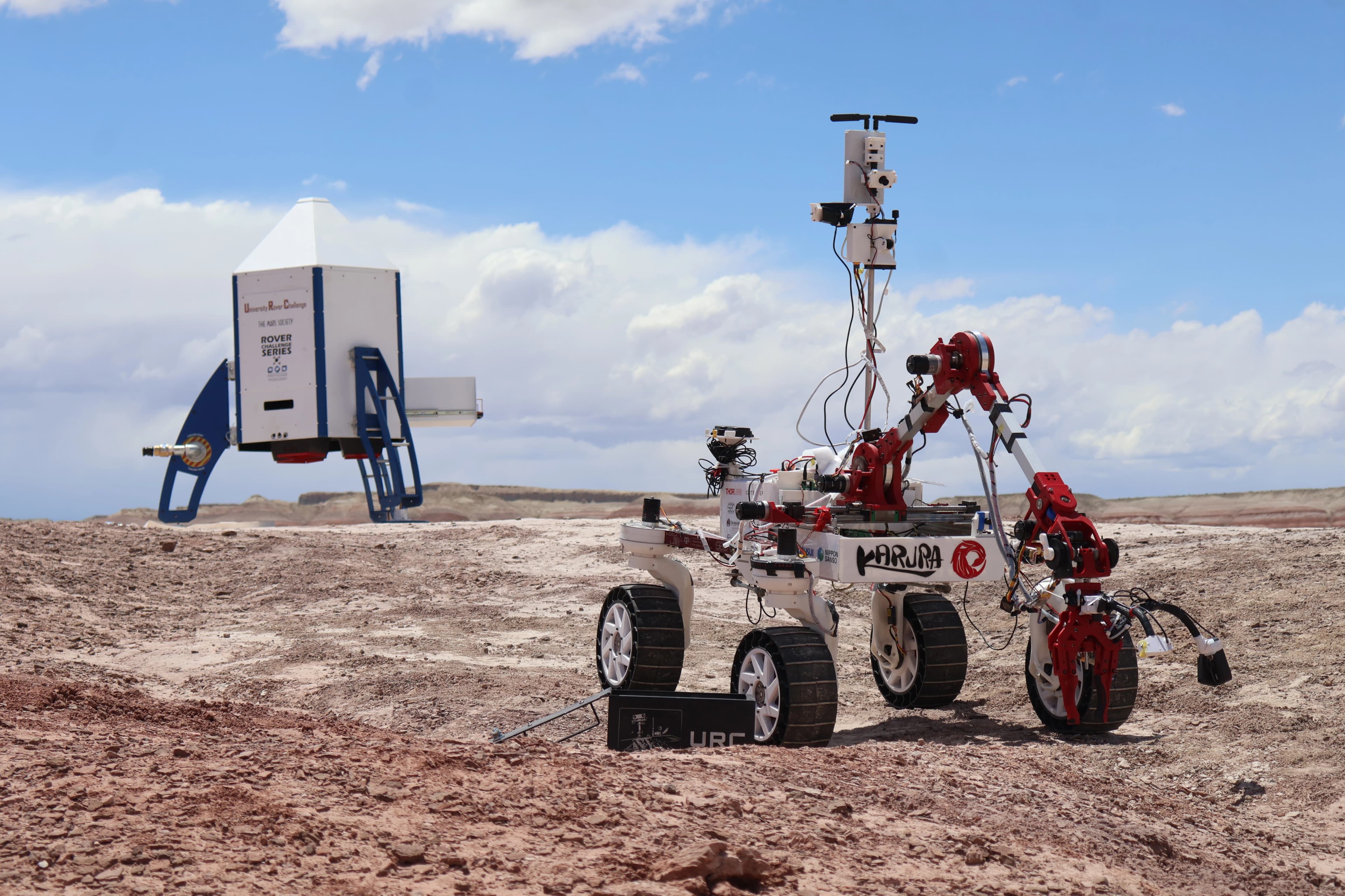
KARURA III
URC System Acceptance Review: qualified
Third-generation platform refining the proven KARURA II architecture with an emphasis on robustness, maintainability, and autonomous capability. Retained the centralized CAN-bus electrical system and 5-DOF arm while integrating enhanced navigation, sensing, and system redundancy features.
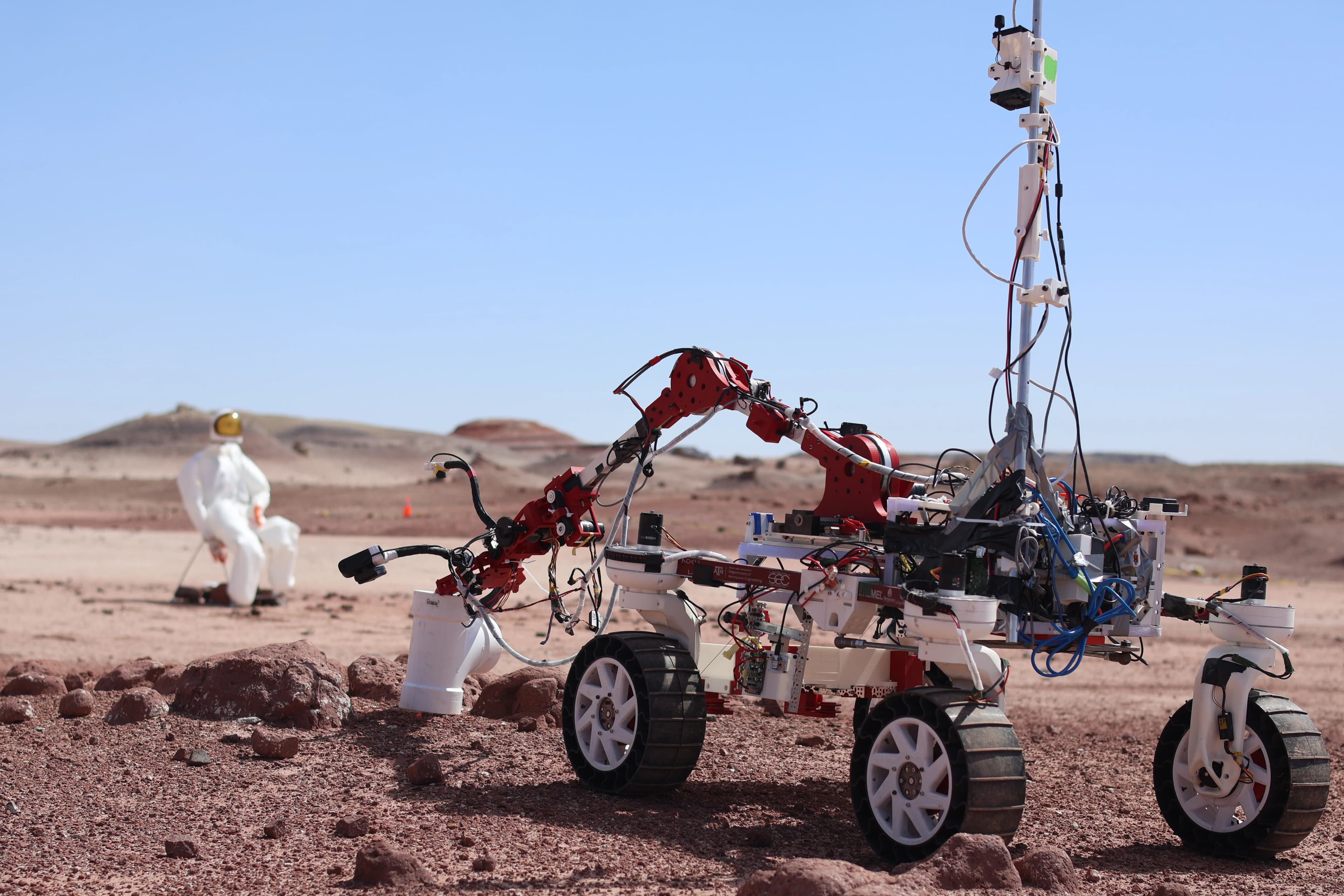
URC Task
Breakdown
The University Rover Challenge scores teams across four mission categories. Each task is evaluated against Mars-analog conditions in the Utah desert, with scoring weighted by task completion percentage and time.
Autonomous Navigation
Rover must navigate 1+ km of rocky Mars-analog terrain, identifying and reaching GPS waypoints without any human intervention.
No-comms zone for portions of the run. Terrain includes loose rock, slopes, and dry river beds.
Equipment Servicing
The rover must operate a cache of hand tools, including levers, buttons, and valves, using only the robotic arm and end-effector.
Requires sub-centimeter arm precision. All tools resemble real-world industrial hardware.
Extreme Retrieval
Navigate extreme terrain gradients and narrow passages to retrieve a cache object from a designated location and return it to base.
Maximum slope angles exceed 40°. Terrain designed to challenge all 4 wheels simultaneously.
Science Mission
Identify, document, and collect soil and rock samples from a designated site. Perform onboard analysis to detect potential biosignatures.
Samples must be documented in-situ with GPS coordinates, images, and onboard spectral analysis.
Subsystem
Inventory
4-wheel independent drive · Rocker-bogie passive suspension · Brushless DC motors · Differential steering geometry
6-DOF serial manipulator · Custom end-effector · Joint encoders · Tool-change interface · Force estimation via current sensing
Multi-cell LiPo architecture · CAN-bus backbone · Custom PCB motor controllers · 5.8 GHz RF comms · Redundant E-stop
ROS2 Humble · Nav2 planner · SLAM Toolbox · Stereo depth estimation · YOLO-based object detection · Operator GUI
Portable spectrometer · Soil drill + passive scoop · Macro camera · GPS coordinate logging · Onboard analysis protocol